
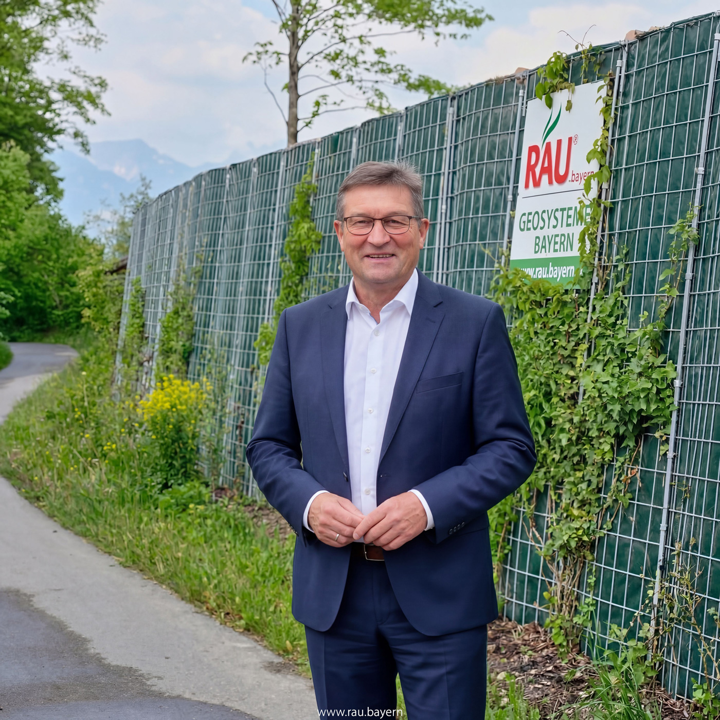
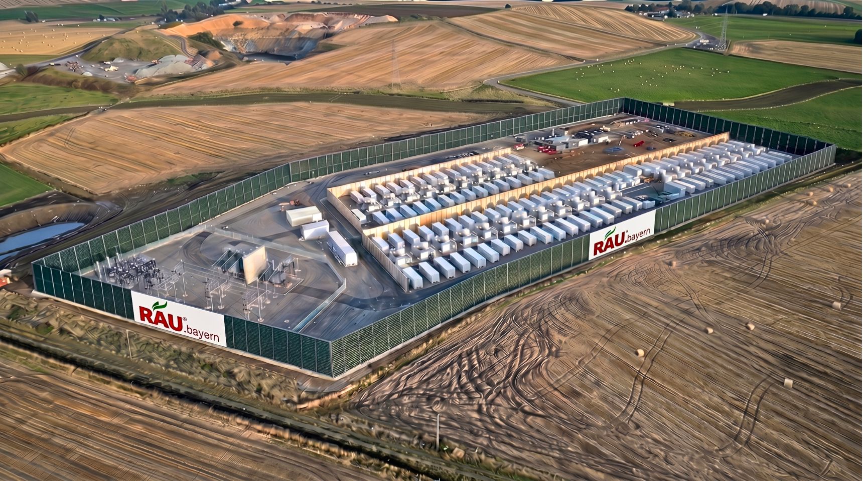
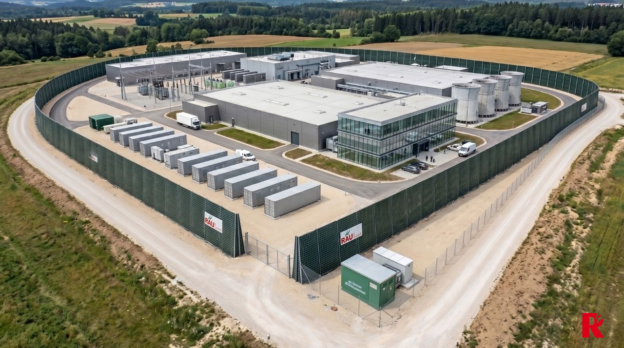
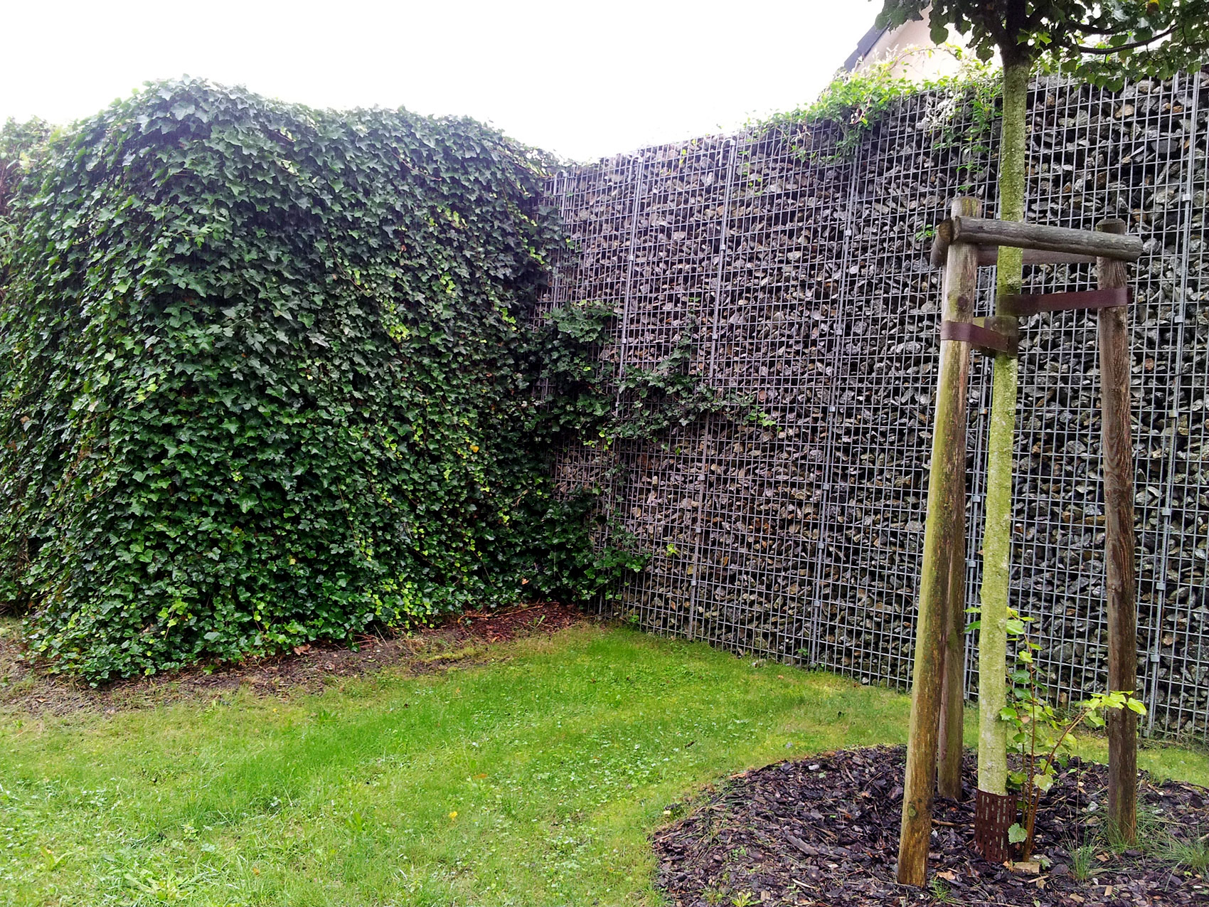
In BESS systems, inverters and transformers are shielded against noise emissions by placing a highly absorbent noise barrier directly against the units, which blocks the tonal components of the inverters and the hum of the transformers. RAU.bayern uses the RAU Bess noise barrier system directly on the inverter and transformer array for this purpose. In addition to fan noise, inverters generate tones at the switching frequency that are perceived as disturbing by residents and can be assessed with a penalty factor for tonal content according to TA Lärm. Transformers contribute a low-frequency hum. We position the wall so that both sources are shielded without obstructing the cooling airflow to the units. The vegetation at the base of the wall requires no irrigation; for narrow transformer fields, we use the RAU Rock Extensiv with a minimum width of 13 cm.
Why are the tonal noises produced by inverters acoustically problematic?
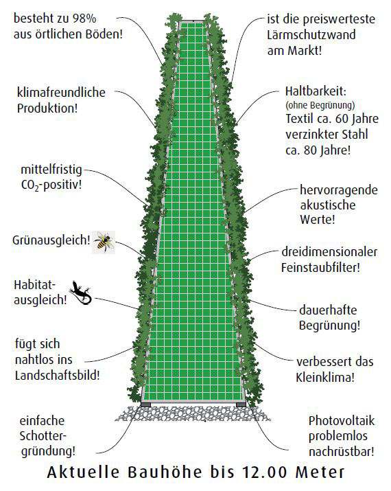
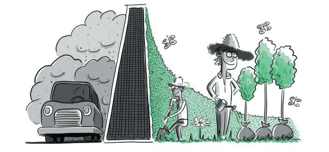
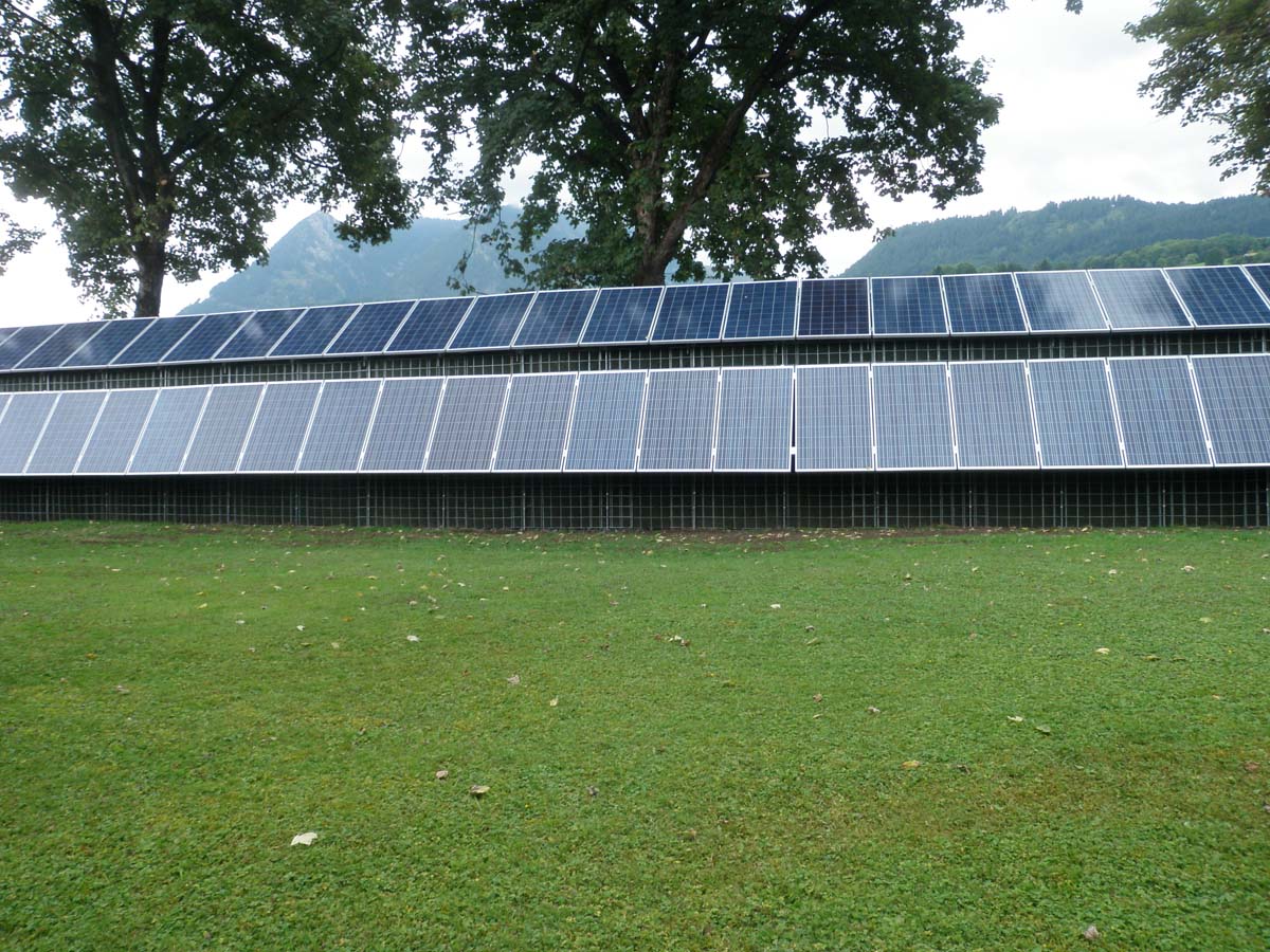
Tonal noises from inverters are acoustically problematic because individual prominent tones resulting from the switching frequency remain clearly audible even at low overall levels, and the TA Lärm (Technical Guidelines for Noise) stipulates a surcharge on the assessment level for tonal noises. For the operator of a battery storage system, this means that the noise exposure limit at a residential building is reached more quickly than the fan noise level alone would suggest. A noise barrier reduces these components if it interrupts the direct propagation of sound from the inverter to the point of exposure and absorbs the sound energy at its surface rather than reflecting it. Our highly absorbent wall systems are designed for this purpose; a reflective wall would direct the sounds toward the opposite container wall and allow them to escape elsewhere. We therefore position the wall section as close to the inverter array as maintenance and cooling airflow permit, and extend it laterally beyond the array to prevent sound diffraction around the wall ends. Our overview of RAU.bayern’s noise protection systems shows which system variants are suitable for this purpose. The operator’s acoustic report remains the authoritative source for assessing sound levels; we provide the wall geometry that the expert uses in their forecast.
Where should the wall be located in relation to the transformer and inverter array?
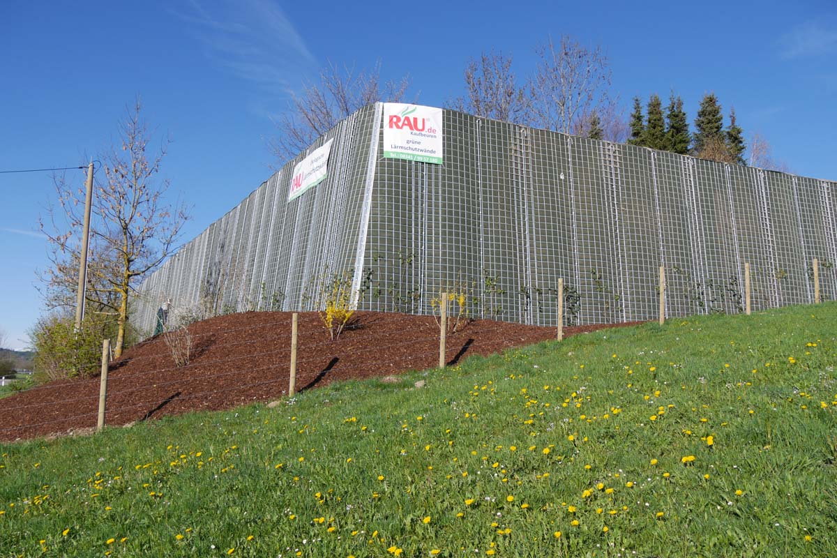
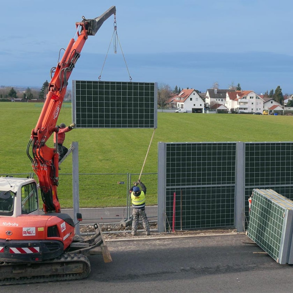
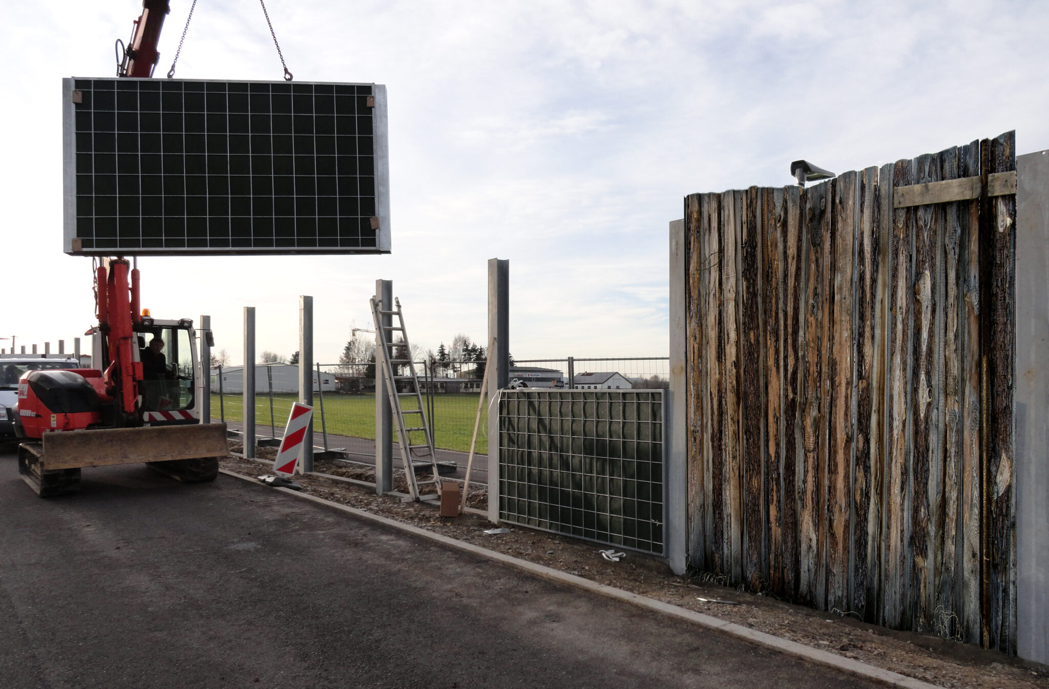
The wall should be located on the side of the transformer and inverter array that faces the nearest exposure point, and as close to the units as possible, because shielding near the source requires a lower wall height. In the case of transformers, their hum also contains low-frequency components that are diffracted around the ends of the wall and over the wall crowns; therefore, we design the section near the transformer to be taller and longer on the sides than the section near the container array. At the same time, the wall must allow for maintenance access to the transformer and inverters and must not obstruct the cooling airflow from the units. We solve this with staggered wall sections or integrated noise-reduction doors, such as those we installed in a climate wall system in Pfaffenhofen an der Ilm. For narrow strips between the substation and the property line, the RAU Rock Extensiv system—with a minimum width of 13 cm—is ideal. The vegetation at the base of the wall grows without irrigation; the wall structure is filled with soil sourced on-site and maintains its volume. Existing transformer stations with old fencing can be retrofitted using the existing support structures; for this, we use the RAU Renovation system, which is installed by our service teams.


